
A New Method for Monitoring Scattered Stray Light of an Inner-occulted Coronagraph
2024-03-22 04:11DaYangLiuHongXinZhangMingZheSunZhengHuaHuangLiDongXiaWeiXinLiuandHuiFu
Da-Yang Liu, Hong-Xin Zhang, Ming-Zhe Sun, Zheng-Hua Huang, Li-Dong Xia, Wei-Xin Liu, and Hui Fu
1 Shandong Provincial Key Laboratory of Optical Astronomy and Solar-Terrestrial Environment, Institute of Space Sciences,Shandong University, Weihai 264209,China; sunmingzhe2003@126.com
2 Changchun Institute of Optics, Fine Mechanics and Physics, Chinese Academy of Sciences, Changchun 130033, China
Received 2023 July 5;revised 2023 September 7; accepted 2023 September 22; published 2024 February 7
Abstract The scattered stray light of a coronagraph is a type of stray light that is generated by the objective lens as its surface defects are irradiated by sunlight.The defects mainly include dust and blemishes on the lens surface,microroughness of the lens surface, and impurity and inhomogeneity of the glass.Unlike the other types of relatively stable defects introduced when the objective lens is being manufactured,the scattered stray light caused by dusts on the lens surface is difficult to quantify accurately due to the disorder and randomness of the dust accumulation.The contribution of this type of stray light to the overall stray light level is difficult to determine through simulations and experiments.This can result in continuous deterioration of the stray light level of a coronagraph and thus affect the observation capabilities of the instrument.To solve this issue, through analyzing the forming mechanism of scattered stray light and ghost image generated by the inner-occulted coronagraph, we propose a novel method to monitor the scattered stray light from dusts by utilizing different stray light correlation coefficients.In this method, we first simulate and measure the level of stray light from the ghost image of the objective lens, and then determine the flux ratio of scattered light and ghost image on the conjugate plane.Although the flux ratio varies with the accumulation of dusts on the lens surface,it remains constant on the image plane.Therefore, the level of dust scattering light on the image plane can be obtained by using this ratio together with the level of ghost image stray light.The accuracy of this method has been validated in a laboratory by applying the objective lens with numerous surface cleanliness levels.
Key words: Sun: corona – Sun: atmosphere – instrumentation: miscellaneous – methods: analytical – techniques:image processing
1.Introduction
In the space era,numerous satellites flowing in the outer space of the Earth are vulnerable to eruptions starting from the Sunʼs atmosphere.Therefore, monitoring the disturbances in the solar corona, the outmost layer of the Sunʼs atmosphere, is crucial to protect our high-tech society (Chen 2013; Wang & Ji 2013; Su& Gan 2014).However, the Sunʼs corona, extending from near the solar limb to tens of solar radii, is extremely thin and thus emits less than a millionth the brightness of the Sunʼs surface(namely the photosphere) (Markus 2004; Zhao et al.2009).To monitor the corona, it relies on a specially-designed instrument,the so-called coronagraph, which blocks the radiation directly from the solar disk and allows the extremely-faint corona to be seen(Gnevyshev et al.1967;Zhang et al.2009;Sun et al.2014).The inner-occulted coronagraph blocks direct sunlight by the inner occulter at the focus of the objective lens.Thus, the faint coronal radiation can be imaged on the detector.However, due to the high-level noise, to image the corona is challenging.A major issue is those stray lights resulting from the optical system,which can easily overcome the brightness of the corona.
The study in this article mainly focuses on the measurement of the scattered stray light in the objective lens of an innerocculted coronagraph.In an inner-occulted coronagraph, the objective lens is directly exposed to sunlight, and thus it will produce high-intensity scattered light, while the scattered light produced by the other lenses (such as the field lens, etc.)is far lower and normally negligible since they are not directly exposed to sunlight.These objective lens scattered lights are one of the major factors that seriously affect the imaging quality and the signal-to-noise ratio of coronal observations.Therefore, to measure the scattered stray lights from the primary lens at the image plane is important to judge whether the surface processing and cleanliness of the objective lens meet the requirements of the coronal observation.The scattered sources of the objective lens mainly include surface finishes,dust contaminants,impurities,and material discontinuity in the glass.Within these factors, the scattered lights caused by surface roughness, impurities and material discontinuity in the glass are fixed and usually not changed after processing of the lens (Bennett 1985).By contrast, the dust contaminants are disordered, and thus the resulted scattered lights are randomly changed with time and cleaning procedures.One requires to monitor this kind of scattered lights routinely.
Since the first coronagraph invented in 1930,many researchers have put a great effort with a series of measurement and calibration on the stray lights from the primary lens.Gordon Newkirk explored the effect of the quality of the surface and the glass materials of the primary lens to the scattered light intensities.He found that surface quality can significantly affect the level of scattered stray lights while different refractive index of the glass material has little impact (Gordon & David 1963).After testing the main mirror scattered light intensity of the main mirror of the coronagraph with different surface qualities at various scatter angles, R.N.Smartt found that high-quality polishing of the objective lens surface resulted in a significant decrease in surface scattered light intensity by almost one order of magnitude obtained by Hostetter and Smartt for the other coronagraph objective lens (Smartt 1980).By comparing the level of total stray light in the coronagraph generated by the ultrasmooth objective lens, with the level of coronal signal light, the authors assessed the reliability of utilizing this lens for coronal observations (Clarence et al.1996).With the development and optimization of modern glass materials,the scattered light caused by glass impurities and material non-uniformity in high-quality lenses is normally negligible.Advanced magneto-rheological polishing technology can reduce the surface roughness of the object lens to sub-nanometer levels,greatly reducing the scattered light caused by the roughness.Studies have shown that when the surface roughness of an inner-occulted coronagraph objective lens is less than 0.5 nm, the level of scattered stray light is approximately 10-6,which can meet the requirement of groundbased coronal observations(Thompson et al.2003).At this point,the problem of stray light in the coronagraph caused by the surface roughness,impurities,material non-uniformity,and other factors in the objective lens has been largely resolved.However,the above-mentioned studies mainly focuses on the relationship between the surface quality of the objective lens, the glass material,and the scattered stray light of the coronagraph.During those testing, researchers made efforts to remove the scattered contribution of dust on the objective lens surface as much as possible, so the impact of dust scattered stray light level in the coronagraph could not be quantified.
The scattering of dust on the objective lens surface is one of the main factors affecting the stray light level in the coronagraph.During normal operation, environmental dust adheres to the objective lens surface and accumulates, leading to a continuous increase of the overall stray light level in the coronagraph.To quantify the impact of dust scattering, Hulst et al.simplified the dust scattering model on the objective lens surface to a spherical particle scattering model (Van 1981).Thompson calculated the level of scattered stray light for the STEREO satellite COR1 coronagraph using simulation.He found that if the object lens surface is super-smooth (surface roughness equals 0.3 nm),when the cleanliness of the objective lens surface changes from Class100 to Class500, the overall level of stray light in the coronagraph increases from 10-6to 10-4(Thompson et al.2003).However, his simulation did not start from the actual distribution of dust on the objective lens surface, and the simulation values provided by the object lens scattering model can only approximately describe the range of stray light levels due to dust scattering.Nelson (2006)demonstrated that dust is the main source of scattered light in the HAOʼs MK4 coronagraph.At the same time, in practical observations of the coronagraph,the uncertainty in the level of stray light due to dust scattering can lead to sustained fluctuations in the signal-to-noise ratio of coronal observation data, making it challenging to accurately retrieve the coronal intensity (Zhang et al.2022).Sha et al.(2023) conducted a study on the scattered light from the objective dust using the Lijiang 10 cm Coronagraph.They obtained the distribution pattern of scattered light with respect to the distance from the Sun by measuring the cleanliness of different objective surfaces, and completed the scattered stray light correction of solar corona images.This study has enhanced the accuracy of coronal intensity inversion to a certain extent.However, the accuracy of the proposed correction method is limited by the contamination level of dust on the surface of the coronagraph.Therefore, monitoring and quantifying the scattered light from dust on the coronagraph have become even more important.
Due to the randomness and disorder of dust on the objective lens surface,the scattered stray light level in the coronagraph due to dust is difficult to quantify.Given this difficulty, this present study proposes a method for monitoring the scattered stray light level in an inner-occulted coronagraph.The method detects the radiative flux ratio of the scattered light and the ghost image at the imaging plane of the Lyot stop, and then combines the simulated ghost image radiative flux to obtain the radiative flux of scattered light due to dust on the coronagraphʼs image plane.The Lyot stop is the aperture stop of the coronagraph optical system and imaging at this position is equivalent to imaging at the objective lens surface position.According to the aperture stop characteristics,the total radiative flux at the Lyot stop is equal to that on the coronagraph image plane,and it can be assumed that the radiative flux ratio of scattered light due to dust and ghost image stray light is consistent at both the Lyot stop and the image plane.Therefore, when the radiative flux of the ghost image on the coronagraph image plane is determined, the radiative flux of scattered light due to dust on the image plane can be directly calculated from this radiative flux ratio at the Lyot stop.Due to the effect of defocusing, the intensity distribution of scattered light due to dust on the coronagraph image plane is approximately uniform.Therefore, the irradiance on the image plane can be calculated from the radiative flux and the ratio of this irradiance to the irradiance of direct sunlight on the image plane is stray light level caused by dust.The radiative flux of the ghost image on the image plane can be obtained through simulation,and the accuracy of the simulation can be verified by comparison with the experiments.Since the ghost image stray light level usually does not vary with the incident light once the optical system has been determined, the scattered light level due to dust can be monitored in real-time without affecting normal scientific observations by using a prism to deflect the light path and imaging the objective lens surface in real-time.Since both the ghost image and scattered light due to dust are generated by direct sunlight, this method is not affected by changes in direct sunlight or atmospheric scattering,giving an accurate and robust results.

Figure 1.Schematic diagram of the operating principle of the CMP-II-SICG prototype.
This study focuses on the prototype of a spectroscopic imaging coronagraph using the design of that for the China Meridian Project Phase Two (CMP-II).The coronagraph features an object lens with a diameter of 70 mm, a focal length of 989 mm, an fnumber of 18.7,and a field of view ranging from 1.05 to 1.5 R⊙,and it images the corona with the Fe XIV emission line(530.3 nm).The organization of this article is as follows: In Section 2, the principle of the inner-occulted coronagraph is briefly introduced.Section 3 presents the simulation results of the ghost image on the Lyot stop and image plane of the coronagraph and verifies the results through experiments to obtain the level of scattered light caused by the ghost image.In Section 4,a monitoring method for scattered light caused by dust is described,and the scattered stray light level caused by dust on the image plane is obtained.The reliability of the monitoring method is verified through a test of the total stray light level of the coronagraph under different cleanliness conditions of the objective lens.Section 5 concludes our results.
2.The General Design of the Inner-occulted Coronagraph
The method proposed in the present study is based on the development of a spectroscopic imaging coronagraph (SICG)designed for the CMP-II, and the detection experiments were carried out using the prototype of the SICG.The CMP-II-SICG prototype is a typical inner-occulted coronagraph, and its design principle is shown in Figure 1.The coronal signal is imaged by O1 first on the field stop plane,then reimaged by the following lenses on the image plane.The direct sunlight is focused by the objective lens O1 on the inner occulter D1 where the light from the disk is blocked.The diffracted light from the objective lens diaphragm A1 is imaged onto and blocked by the Lyot diaphragm A3.A2 is the field diaphragm,which determines the field of view of the instrument together with D1.Due to the fact that O1 is exposed to the sunlight, a ghost image is generated from O1 because of multi-reflections.After O2 focusing, the ghost image will be blocked by a Lyot spot D2 located on the front surface of O3.F is a tunable filter used to select a specific corona observation wavelength.The imaging lens O4 refocuses the output beam from F onto the image plane.
3.Simulation and Measurement of Ghost Images
In an inner-occulted coronagraph system, the objective lens is the only lens directly exposed to the sunlight.Therefore, the ghost image generated by the objective lens is the main ghost image in the optical system.In addition, this article only considers the ghost image generated by the second reflection of the front and back surfaces of the objective lens, as the ghost image generated by higher-order reflections is at least three orders of magnitude weaker than that generated by the second order reflection.To simulate the ghost image,it is necessary to calculate the reflectivity of the objective lens.The surface of the objective lens can be modeled as a plane of light with normal incidence for the following reasons: (1) the curvature radius of the objective lens surface is very large; (2) according to the design of the coronagraph, the second order reflection?only in a very small area near the optical axis can reach the subsequent optical system; (3) due to the great distance between the Sun and the earth,the actual incident angle is very small.The maximum incident angle in the external field of view is 16′, and the incident angle of the second reflection is about 48′.The reflectivity difference based on the material of the objective lens(fused quartz)is only about 0.0018%,which can be negligible.Using the simplified model and the Fresnel formula,the surface transmittance and reflectivity of the object lens are obtained as 96.5%and 3.5%,respectively.The second order reflection can be expressed as
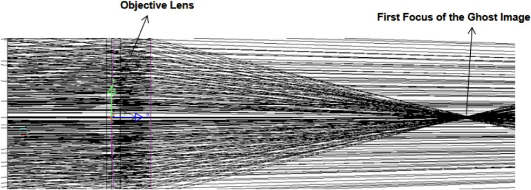
Figure 3.The first focal point of the secondary reflected light of the objective lens.
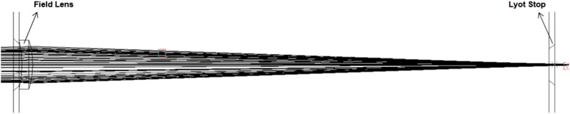
Figure 4.The secondary reflected light of the objective lens is refocused by the field lens at the Lyot stop.
where IGis the intensity of the second reflex light(ghost image)generated by the front and back surfaces of the objective lens;T and R are the surface transmittance and reflectivity of the objective lens,respectively;and I is the intensity of the incident sunlight at the front surface of the objective lens.The coronagraph is modeled as shown in Figure 2.The divergence angle of the light source model is ±16′, which is the average divergence angle of the Sun at the Earthʼs surface,with a band of 10 nm and a central wavelength of 530.3 nm,and a uniform surface light source is used.The Monte Carlo method is used to simulate the ghost image by setting a large number of random rays to propagate in the optical system to obtain the distribution of the ghost image at various positions.The second order reflected light (ghost image) of the objective lens is first focused at a distance of 136.5 mm behind the objective lens(see Figure 3), then focused again by the field lens near the Lyot stop (see Figure 4), and finally diverged on the image plane.
In this article, all the measurements in the optical system are normalized to the incident beam.2.1 billion simulated rays are used to obtain the normalized ghost image distribution at the Lyot stop and image plane,as shown in Figure 5.The left panel of Figure 5 shows the distribution of the ghost image at the Lyot stop, where the ghost image presents a ring-shaped intensity distribution due to slight defocus of the ghost image at the Lyot stop plane,and the center of the ghost image appears darker due to the attenuation effect caused by the inner-occulted disk.The right panel of Figure 5 shows the distribution of the ghost image on the image plane, where the ghost image is almost uniformly distributed in the annular field of view of the coronagraph,which is similar to the scattered stray light of the objective lens blocked by the inner-occulted disk.The simulation results show that the level of ghost image stray light on the image plane of the coronagraph is 7.80×10⁻⁷.The simulation results are then compared with the experiments in the laboratory to verify the accuracy of the simulation.

Figure 5.Ghost image stray light level at the Lyot stop plane (left panel) and the image plane (right panel).
The experiment of ghost and stray light levels in the coronagraph is conducted in a 1000-class cleanroom.The cleanroom consists of a light source room and a detection room, connected by a long optical channel more than 10m in length.To obtain a simulated beam of sunlight, a simulated system is built in the light source room, and the beam is fully filled in the instrument aperture after passing through the long optical path and entering the CMP-II-SICG prototype.The overall experimental setup is shown in Figure 6.The simulated solar system consists of a xenon lamp, opal glass, a simulated solar aperture, and a parallel light tube.The simulated solar aperture is placed at the focus of the xenon lamp and has a diameter of 14.97 mm.After collimation by a parallel light tube with a focal length of 1602.8 mm, a parallel beam with a divergence angle of ±16′ is obtained.The beam divergence angle of the simulated light beam is consistent with the average divergence angle of sunlight observed from the Earth.A 10 nm bandwidth neutral density filter(central wavelength 530 nm)is placed at the back of the CMP-II-SICG prototype in place of the Lyot filter, and the test image is captured by an Andor Marana sCMOS camera.
The ghost image stray light level is obtained by measuring the difference in stray light levels at the image plane of the coronagraph under the conditions of blocking and unblocking ghost images.The ghost image is blocked by a flat glass with a center coating of absorbing material placed at the Lyot stop plane.The radius of the absorbing material is 0.5 mm as shown in Figure 5, and the ghost image can be completely blocked.First, the stray light intensity at the imaging plane of the coronagraph under the condition of blocking ghost images is measured.Then, the entire coronagraph system is translated,and the intensity of the simulated Sun at the image plane is measured,and the ratio of the two is the stray light level under the condition of blocking ghost images.The same measurements are repeated while the Lyot stop is removed, in order to obtain the stray light level under the condition of unblocking ghost images.The measurements at these two conditions are shown in Figure 7.To compare the changes of stray light levels under the two conditions, Figure 8 shows the stray light level along the x and y axes at the center of the coronagraph field of view for each condition.Figure 9 shows the difference in the stray light level between the two conditions, which actually gives the ghost image stray light level.
According to the experiments, the average stray light level caused by ghost images is 8.20×10⁻⁷, which is very close to the simulation result (7.80×10⁻⁷).The slight difference between the laboratory and the simulation results is due to the fact that the Lyot spot (the absorbing material that blocks ghost images)also blocks a small portion of the scattered light from the center of the objective lens.Therefore, we can conclude that the ghost image stray light level in the coronagraph is approximately 8.0×10⁻⁷.The ghost image stray light level normally remains unchanged after the completion of the coronagraph.
4.The Monitoring Method for Dust Scattered Stray Light
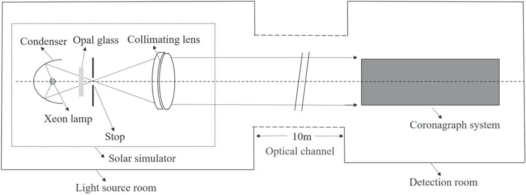
Figure 6.Schematic diagram of simulated sunlight generating device.
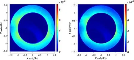
Figure 7.Coronagraph stray light level distribution measured with (Left) and without (Right) Lyot spot.
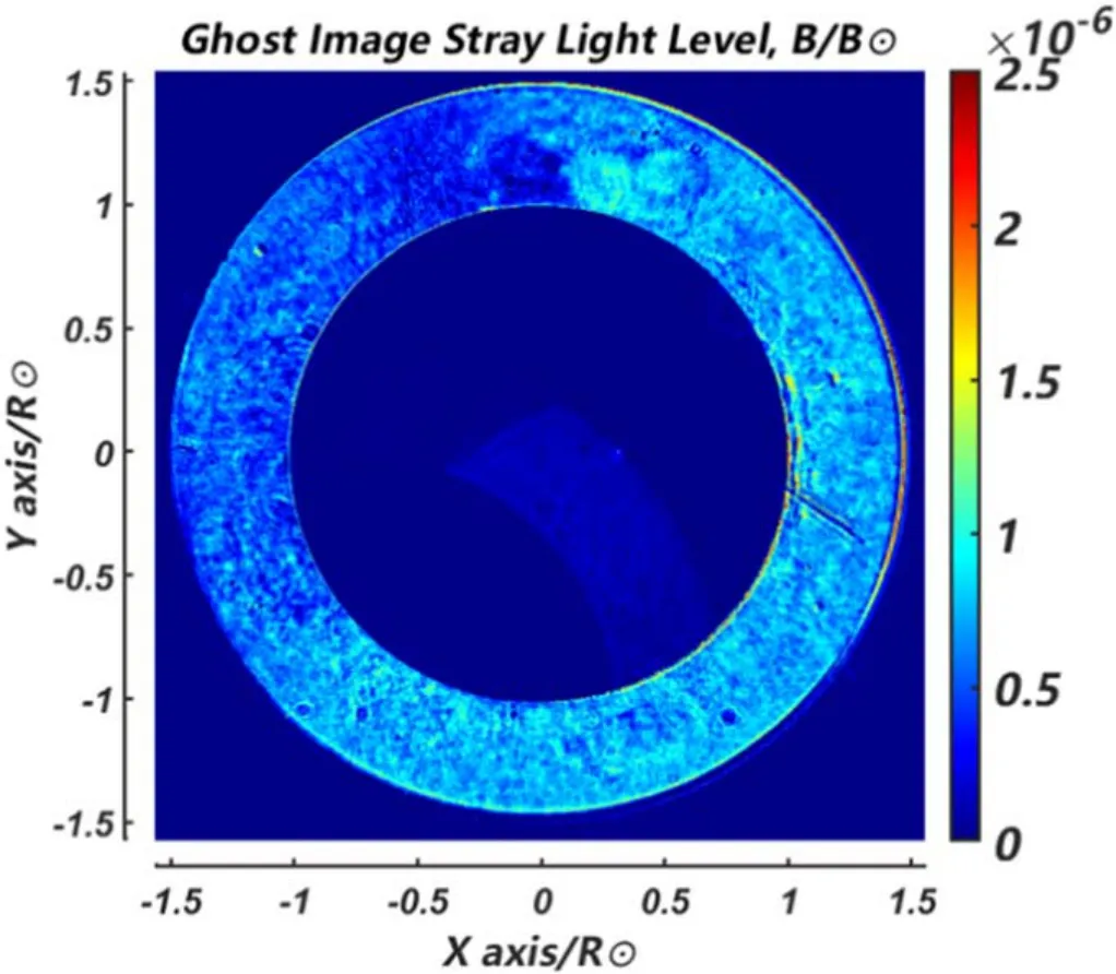
Figure 9.2D distribution image of secondary reflected stray light level.
The monitoring method for dust scattered light is achieved by using the ghost image stray light to monitor the dust scattered light.In Section 3, we show that the ghost image's stray light level in the coronagraph can be obtained.Since the radiation flux ratio between the ghost image and the dust is constant at the Lyot stop plane and the image plane, the dust scattered stray light level at the image plane can be evaluated using the ghost image stray light level given by the simulation and the ratio of radiation flux between the dust scattering points and the ghost image measured on the Lyot stop plane.
According to the optical structure of the coronagraph,the light from the solar disk is blocked by the inner-occulter after being focused by the objective lens, while the dust scattered light on the surface of the objective lens is converged by the field lens on the plane at the position of the Lyot stop.In practice,a detector cannot be placed at the position of the Lyot stop because not enough room is left there.Instead, a detector is placed at the optical conjugate position behind the Lyot stop, which is the imaging position of the Lyot stop.This position is also the aperture stop plane.The flux ratio between the ghost scattered light and the dust scattered light on this plane is the same as that on the image plane.Since the dust and ghost image are focused on this plane, their scattered lights can be well separated and then the flux ratio can be obtained.Because the ratio between the ghost image (ΦG) and the dust scattered lights (ΦS) remains constant in the following optical system, combined with the ghost image stray light level of the coronagraph for the image plane (EG) obtained from the simulation as described in Section 3, the dust scattered light level at the image plane (ES)can be calculated as ES=ΦS/ΦG×EG.The flowchart of the monitoring method is shown in Figure 10.
Figure 11 shows the image of the Lyot stop plane taken in the laboratory,in which the ghost image appears as a bright circular ring near the center of the field of view, consistent with the simulated ghost image shown in Section 3.The randomly distributed scattered points in the field of view are formed by the convergence of scattered light from dust on the surface of the objective lens.From this image,it is clear that the radiation flux of the scattered points and the ghost image spreads in a very large range, which might exceed the dynamic range of the detector.When the large scattered points are saturated, the smallest one might still be below the detecting limit.Therefore,it is impossible to measure the radiation flux of all the scattered points with different diameters in one exposure.Since the linearity of the Andor Marana sCMOS detector used in the experiment is greater than 99.7%,this problem can be overcome by using multiple exposures.In the test,two methods of multiple exposures were used.The first method involves capturing multiple images with the same short exposure time and then overlaying them for processing,so that the larger scattered points do not appear saturated in the detector.However, a short exposure time can result in insufficient exposure for weak scattered points and thus a larger error.The second method involves capturing images with different exposure time, so that the scattered light from different diameter scattered points can be obtained from images with different exposure times, and both strong and weak scattered points can be exposed sufficiently.The saturated pixel values in the long exposure images are replaced with the corresponding pixel values in the short exposure images multiplied by the ratio of exposure time.In the experiment, it was found that the maximum exposure time without saturated scattered points was about 50 ms, which was set as the exposure time for the first method and the minimum exposure time for the second method.
After processing the imaging data of the Lyot stop plane,we found that when the first method was used with 200 exposures for overlying, and the maximum exposure time for the second method was set to 10 s, the weakest scattered points in both methods had sufficient irradiance in the image.In Figure 11,the scattered light from the coronagraph objective lens includes the scattering from dust particles (random bright spots in the image) and surface roughness (dark background in the field of view).When considering only the influence of dust scattering on the instrument, we have to extract the scattered points.
In the first method, the dark field and cosmic rays were first removed from each exposure.Then, the scattered points exceeding the intensity of the dark background in the image were extracted.Finally, all 200 exposures were overlaid to obtain the composite image (see Figure 12, left panel).The total DN values of the ghost image (bright ring) and scattered points were extracted from the overlaid image, corresponding to 7.68×10⁸photons and 3.46×10⁹photons, respectively.
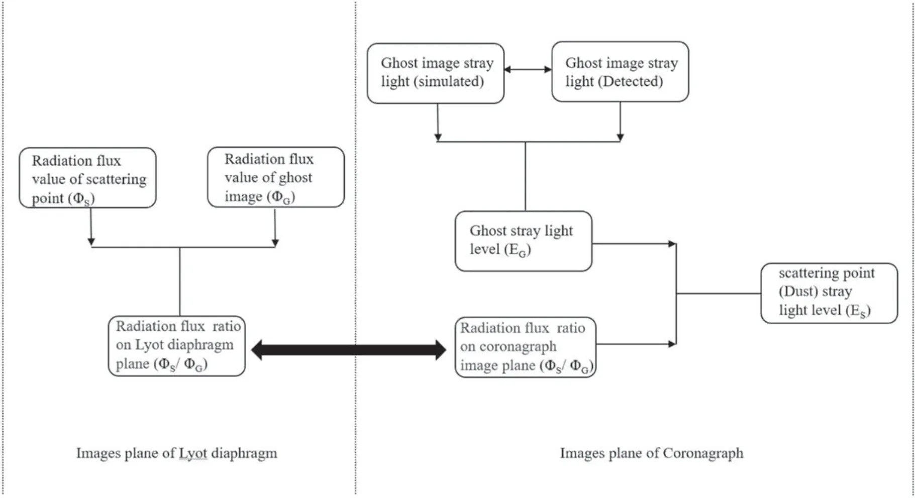
Figure 10.Flowchart of the dust scattering stray light level monitoring method.
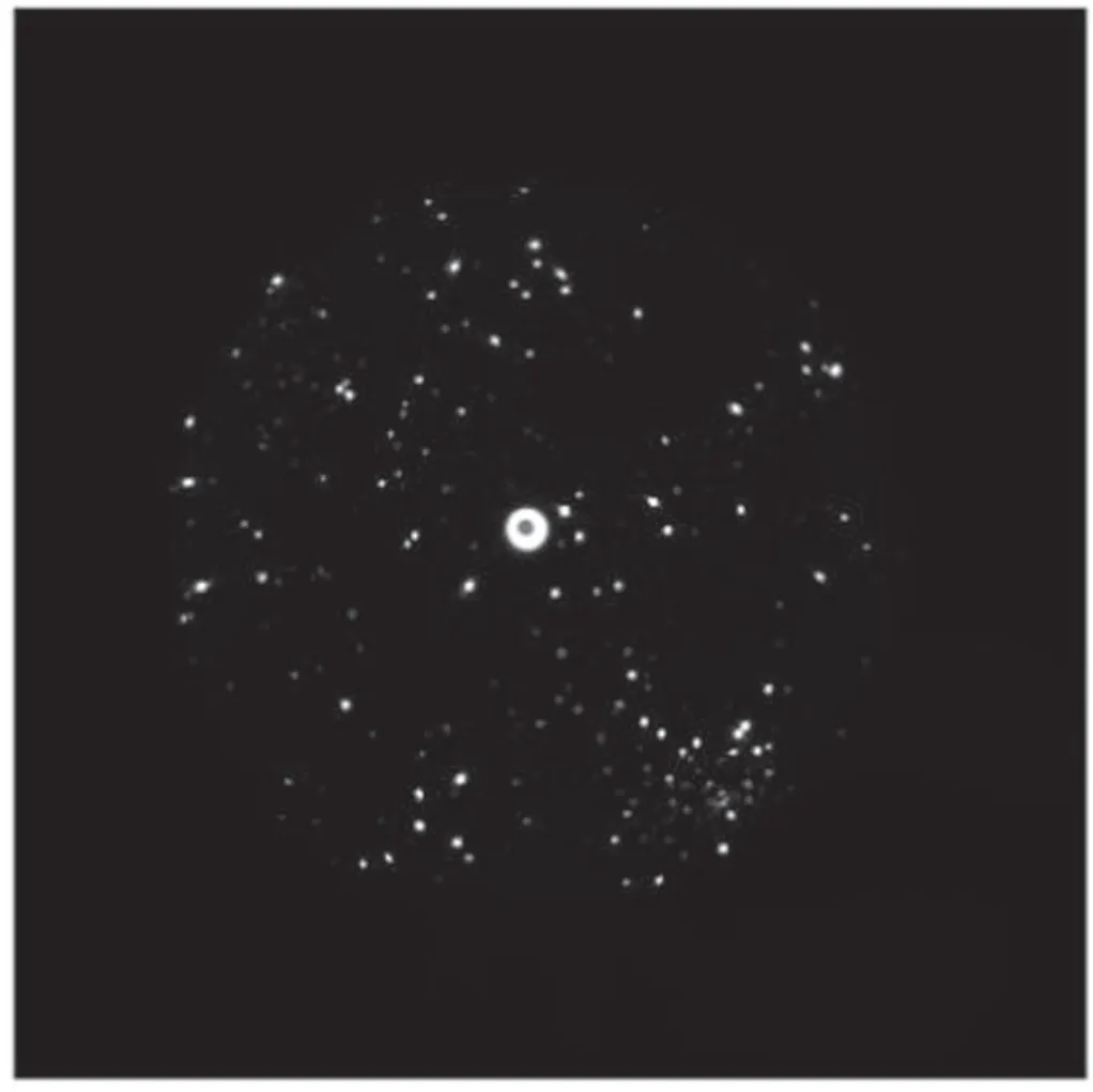
Figure 11.Scattering points and ghost image from the objective lens at the Lyot stop imaging plane.
In the second method, starting from the image with the largest exposure time, the saturated pixel values in the long exposure image were replaced with the corresponding nonsaturated pixel values from the decreasing exposure time image, multiplied by the corresponding exposure time ratio.This replacement process was done sequentially,decreasing the exposure time until all exposures were replaced.This resulted in a composite image representing the longest exposure time(i.e.,10 s)(see Figure 12,right panel).Similarly,the intensities of the ghost image and scattered points were extracted from the composite image, measuring 7.71×10⁸and 3.41×10⁹photons, respectively.We can see that the results obtained from the two methods are in good agreement.
As mentioned earlier, the ratio of radiation flux between dust scattering and ghost image is the same at the Lyot stop plane and the coronagraph image plane.The aforementioned measurements obtained a radiative flux ratio of approximately 4.51 between dust scattering and ghost image at the Lyot stop imaging plane,which remains constant on the coronagraph image plane.In Section 3,we have determined that the stray light level of the ghost image on the image plane is 8×10⁻⁷.Therefore,we can obtain a dust scattering stray light level of approximately 3.61×10⁻⁶for the current experiment.
To verify the effectiveness of our monitoring method, we conducted tests on several groups of objective lenses with different surface cleanliness conditions (referred to as C1–C4 for simplicity)at the Lyot stop plane.Based on the monitoring method, we obtained the ratio of radiation flux (K=ΦS/ΦG),the level of dust scattering light (ES), and the difference in scattering light level ((ΔES).Subsequently, the detector was moved to the coronagraph image plane to measure the overall stray light level of the coronagraph for different objective lens surface cleanliness conditions.Since the stray light levels caused by ghost images and surface roughness scattering from the objective lens are constant,any differences in the stray light levels of the coronagraph for different conditions solely result from the accumulation of dust.The difference in stray light levels of the coronagraph for different objective lens surface cleanliness conditions was measured and denoted as ΔE′.Figure 13 shows the Lyot stop imaging data for objective lenses with various surface cleanliness conditions.Figure 14 presents the variations of the average distribution of stray light levels in the field of view.Table 1 gives the corresponding values obtained from the dust scattering light monitoring method and the measured values.
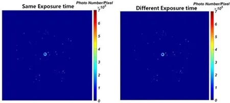
Figure 12.Photon number distributions of scattering points and ghost image of the objective lens at Lyot stop plane.(Left: taking multiple images with the same exposure time; Right: taking multiple images with different exposure times).
From Figure 13, we can see that as the cleanliness of the objective lens surface deteriorates (from C1 to C4), there is an increasing trend in the number and area of scattering points at the Lyot stop imaging plane.The ratio of the radiation flux between scattering points and ghost images increased from 2.87 to 7.94,and the level of dust scattering stray light obtained from the dust scattering light monitoring method increased from 2.31×10⁻⁶to 6.35×10⁻⁶.The overall level of stray light in the coronagraph is determined by measuring the stray light intensity at the coronagraph image plane, which is obstructed by ghost images,and dividing it by the intensity of direct light at the same position after removing the internal baffles.This stray light level is the sum of dust scattering light from the objective lens surface,surface roughness scattering light,and other types of stray light in the detection environment.
Figure 14 presents the average distribution of stray light level along the field of view for the coronagraph under different surface cleanliness conditions of the objective lens.It clearly shows a decrease in the stray light level from the inner to the outer field-of-view, which is the stray light character of the coronagraph optical system.The total stray light level(E’)given in Table 1 is obtained by averaging these values along the field of view as shown in Figure 14.From Table 1,it can be seen that the overall stray light level in the coronagraph increased from 3.75×10⁻⁶to 7.78-6as the cleanliness of the objective lens surface deteriorated.Since the levels of surface roughness scattering light from the objective lens and stray light from the detection environment remain constant under the same measurement conditions, the variation in the overall stray light level of the coronagraph is almost due to the accumulation of dust on the objective lens surface.We provided the values of the dust and total stray light level differences (ΔESand ΔE′) for different conditions of surface cleanliness of the objective lens (see Table 1).The good agreement between these values confirms that the variation in total stray light level is caused by that of dust and also ensures the effectiveness of the method.
During the regular observations of the coronagraph, dust might continuously accumulate on the surface of the objective lens, leading to a continuous deterioration of the instrument’s stray light level.Therefore, real-time monitoring of the dustinduced stray light level in the coronagraph is crucial to ensure the quality of the coronagraph data.In this paper, a technical solution for real-time monitoring of stray light in the coronagraph is constructed using the aforementioned monitoring method, which will be implemented in the CMP-II-SICG.The schematic diagram of the technical solution for the realtime monitoring system of stray light in the CMP-II-SICG is shown in Figure 15.
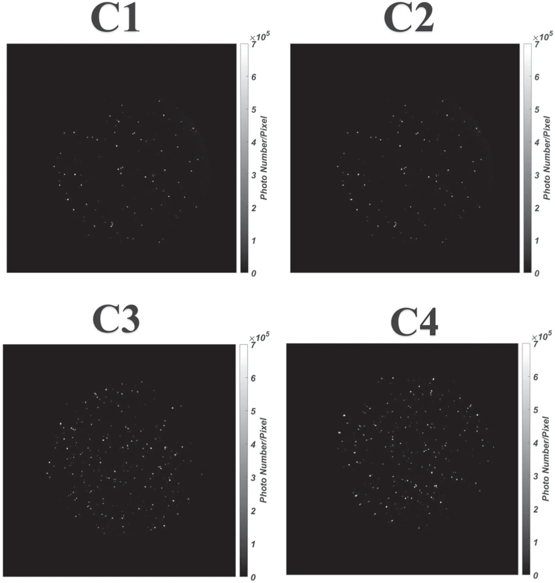
Figure 13.Imaging diagrams under different cleanliness conditions of the coronagraph’s objective lens surface.
The proposed solution involves implementing a beam splitter optical path to the basic design of the CMP-II-SICG.In Figure 15, panel (a) depicts the overall optical design of the CMP-II-SICG, panel (b) is an enlarged view of the middle section of the instrument design, and panel(c) is an enlarged view of the rear section of the instrument body.The design of the stray light monitoring system for the coronagraph is represented by the purple optical path.This design allows for monitoring the status of the objective lens without affecting the main observing optical system of the coronagraph.By using a polarizing beam splitter prism placed in front of the filter, the incident light beam is split,and the split beam is imaged by the monitoring camera with an imaging mirror assembly.This position corresponds to the conjugate imaging plane of the objective lens.By monitoring the ratio of the radiation flux between the scattering points and the ghost image at that position using the aforementioned method, the level of dust scattering stray light in real-time is obtained.By comparing the real-time level of dust scattering stray light with the known coronal signals,the data quality of the coronagraph can be also be monitored and decision-making information can be provided for the cleaning and maintenance processes.
5.Summary

Figure 14.Average stray light level distribution diagram along the field of view direction of the coronagraph under different cleanliness conditions of the objective lens surface.
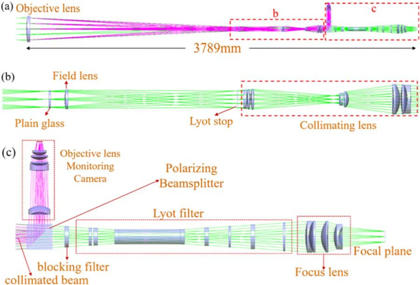
Figure 15.Schematic diagram of the technical solution for real-time monitoring of stray light in the CMP-II-SICG.
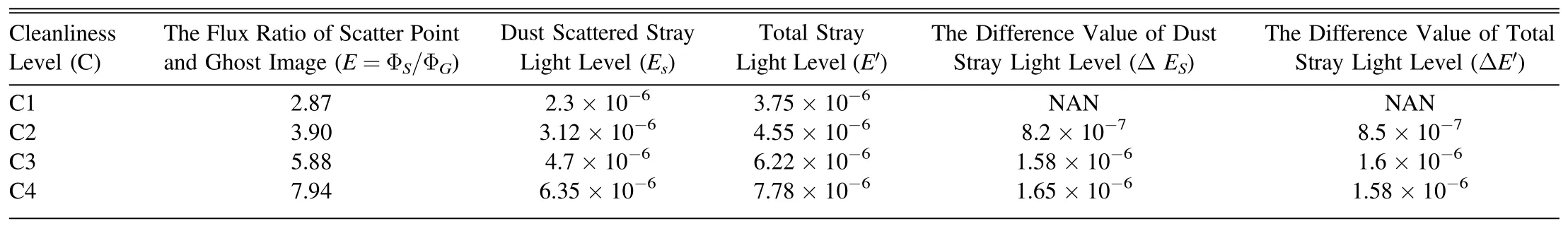
Table 1 Correspondence between the Values Obtained from the Dust Scattered Light Monitoring Method of the Coronagraph and the Measured Values
In this study, we present a new method for quantitatively monitoring the scattered stray light level in an inner-occulted coronagraph.This method evaluates dust scattered stray light level on the objective lens surface includes simulations of the ghost image stray light level on the coronagraph image plane and measurements of the ratio of the radiation flux between dust scattering points and ghost image on the Lyot stop imaging plane.This monitoring method is independent of the intensity of direct sunlight and is therefore not affected by atmospheric scattering light.The method can be applied in realtime stray light monitoring systems for coronagraphs to assess the contribution of the cleanliness of the objective lens surface to the overall stray light, and thus can guide the cleaning schedule of the lens.The method has been successfully applied to the prototype of the spectral imaging coronagraph in the CMP-II and will be implemented to the final construction.This method can quantify the deterioration of stray light level caused by the increase of dust on the objective lens surface.Under conditions where the objective lens is relatively clean,the level of dust scattering stray light is around 2×10⁻⁶.This indicates that the design of the CMP-II-SICG meets the requirements of the project and enables high-quality coronal observations.
Acknowledgments
This work is supported by the National Key R&D Program of China No.2021YFA0718600, the National Natural Science Foundation of China (grant Nos.41904168, 42274227 and U1931122), and the Chinese Meridian Project.
 Research in Astronomy and Astrophysics2024年2期
- Research in Astronomy and Astrophysics的其它文章
- A Fermi-LAT Study of Globular Cluster Dynamical Evolution in the Milky Way: Millisecond Pulsars as the Probe
- Application of Regularization Methods in the Sky Map Reconstruction of the Tianlai Cylinder Pathfinder Array
- Effect of Cosmic Plasma on the Observation of Supernovae Ia
- Variable Stars in the 50BiN Open Cluster Survey.III.NGC 884
- Free Energy of Anisotropic Strangeon Stars
- Data-driven Simulations of Magnetic Field Evolution in Active Region 11429:Magneto-frictional Method Using PENCIL CODE